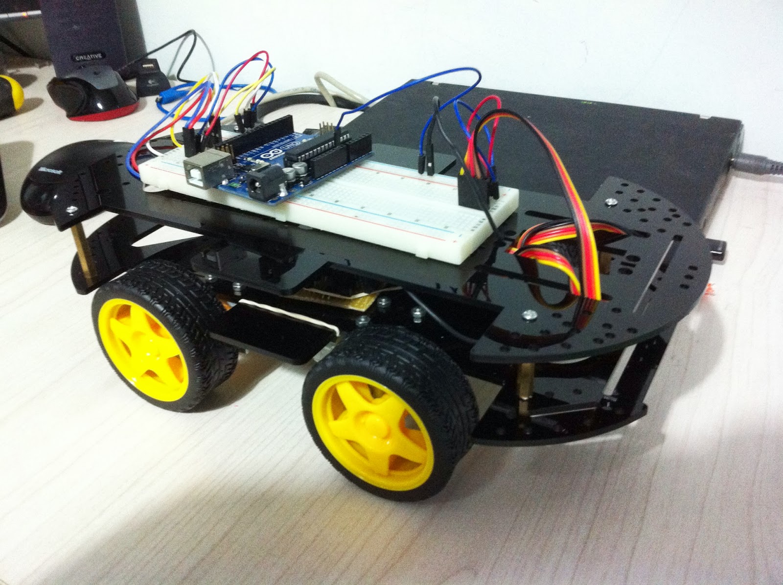
Making the car actually move was not as smooth as I expected. When I got a well constructed circuit for an H-Bridge to control the motors on a breadboard, it took me quite sometime to debug and understand what is not ticking. After making it work on a single motor, I created the PCB.
Time to construct the car and make it run.
I connected the motors to the car body and hooked the wires to the motors:
What you see in the above picture is the bottom of the car, so the motors actually go under the car. On the other side I placed the H-Bride PCB and connected the wires:
I then placed the upper platform of the car to mount a breadboard to continue the testing and hopefully make the cat run.
I took out an Arduino board and connected the pins to the H-Bridge using a breadboard and created a small sketch that will make the car move forward, backwards, rotate left and rotate right, each for 2 seconds.
The first tests didn't make the car move at all. Now that is a bummer. At first I though it's probably the battery, so I hooked them directly to the motor and the motor ran like there was no tomorrow. Back to the drawing board.
The first tests didn't make the car move at all. Now that is a bummer. At first I though it's probably the battery, so I hooked them directly to the motor and the motor ran like there was no tomorrow. Back to the drawing board.
Looking at the schematics I created, I used 100K resistors so I will have a small as possible current leakage. I found a very cool site with a JAVA applet that can do a rather well simulations, check it out (The link has also the code to the H-Bridge circuit that I created):
Just to be clear, when I indicate a leakage I mean the current that passes though the H-Bridge Circuit and does not pass though the motor.
The good solution would be to place a 3 Darlington Transistors together and not just a pair, which would have solved the problem, but this would require a new PCB and throw away the one I already made. Another solution that is not so bad is using lower resistors to allow more current to drive the Transistors and allow more current to flow to the motor. Making the resistors 10K instead of 100K should resolve the problem. This, however, will have a current leakage problem when the motors run. If the input switches, both of them are set to off state there is a very minor leakage (in the PICO rating), when one of them is turned on, there is a leakage current of ~1.3mA. Well, it's not so bad, considering other alternatives I think this is the preferred solution.
OK, got the new 10K resistors replacing the 100K and this indeed did the job.
This is the updated SchematicsDon't want to bore anyone, but I also had a problem of the Arduino getting reset when using the same power supply as the motors. I didn't debug this, but I also decided not to mess with it too much, so I hooked a 9V battery to the Arduino, connected the grounds together with the H-Bridge ground and made the motors run on a 4 AA Cell batteries.
And now for the test. The test went as expected, but I still need to test the motors when I run them with PWM to see if I can make the Car go left and right in different speeds.
The next step would be to use another Arduino board connected to a joystick and wireless transmitter to make a remote control for the car. I will also need a wireless receiver on the car as well.
On last thing, I made a video of the test I did with the car after all the adjustments, enjoy.
The next step would be to use another Arduino board connected to a joystick and wireless transmitter to make a remote control for the car. I will also need a wireless receiver on the car as well.
On last thing, I made a video of the test I did with the car after all the adjustments, enjoy.


No comments:
Post a Comment