Monday, September 30, 2013

Remote Controlling the car

So the car can run and move, now to the fun stuff, to add a remote control to the Car.
First things first, what to use as a remote? I decided to use a Joystick BOB (break out board) module. Look at the picture, does it look familiar? It should, it's the same analogue Joystick you use in the PS/PS2/PS3 controllers. To connect it to the Arduino board it's very simple, the module has 5 pins which are (not in the correct order :)):
1. VCC
2. GND
3. X - Axis
4. Y - Axis
5. Swtich

The connections, well, the first two you know where they go. The X and Y axis goes to the analogue pins of the Arduino. The switch is optional, if you like to use it then connect it to whatever pin on the Arduino.

The X and Y axis are actually POT devices, so when tilting the joystick, the X will have a certain voltage from 0 - 5V corresponding to the tilt and the Y acts the same. 

Great, now the Joystick is connected and the Arduino can read the position of the Joystick, let's try make something run.

Still, the data needs to be sent wireless to the Toy Car. Again, cheap stuff. There are nice 433Mhz transmitter and 433Mhz receiver modules that can be used for this. These modules are really cheap, something like 1.25$ for both a transmitter and receiver.

The thing is on these cheap wireless modules is that they really don't do much.
The transmitter when the data pin goes to HIGH, starts sending a 433Mhz wave signal and that's it. When the pin goes LOW, it stops sending the wave signal.

The transmitter when receiving a wave signal on the 433Mhz band, it turns the data pin HIGH and when there is no signal, it turns it to LOW.

You can understand that these modules will not work out-of-the-box and require some software tuning code. Luckily, there is a nice Arduino library called VirtualWire that does all the fine work of CRC checks and synchronizing the transmission and receiver to a pre-configured baud rate. The library does not support multiple transmitters, or to be more clear a collision detection or avoidance mechanism (for wireless it's CA - Collision Avoidance). I'm not going to go deep into it, but I do have an idea on implementing it myself, but that will have to wait for the other 5 433Mhz module to arrive so I can do some tests.

The transmitter module and the receiver modules do not come with an antenna, so just for the purpose of the tests, I used an alligator clip as an antenna.


Great! Now let's connect everything together. The Joystick will be connected to the first Arduino board along with a transmitter module. It will read the values of the joystick and transmit them, nothing fancy.
The second Arduino will be connected to the Toy Car and the receiver module.

After a few tries from my son (my trustee QA :)) I finalized the correct calibrations, and the car worked nicely.

Here is a demo of my son testing the car:


The sound of glass braking at the end of the video was done by my daughter that dropped a glass by mistake in the kitchen, nothing serious :).

Saturday, September 14, 2013

It can move

Making the car actually move was not as smooth as I expected. When I got a well constructed circuit for an H-Bridge to control the motors on a breadboard, it took me quite sometime to debug and understand what is not ticking. After making it work on a single motor, I created the PCB.

Time to construct the car and make it run.
I connected the motors to the car body and hooked the wires to the motors:

What you see in the above picture is the bottom of the car, so the motors actually go under the car. On the other side I placed the H-Bride PCB and connected the wires:

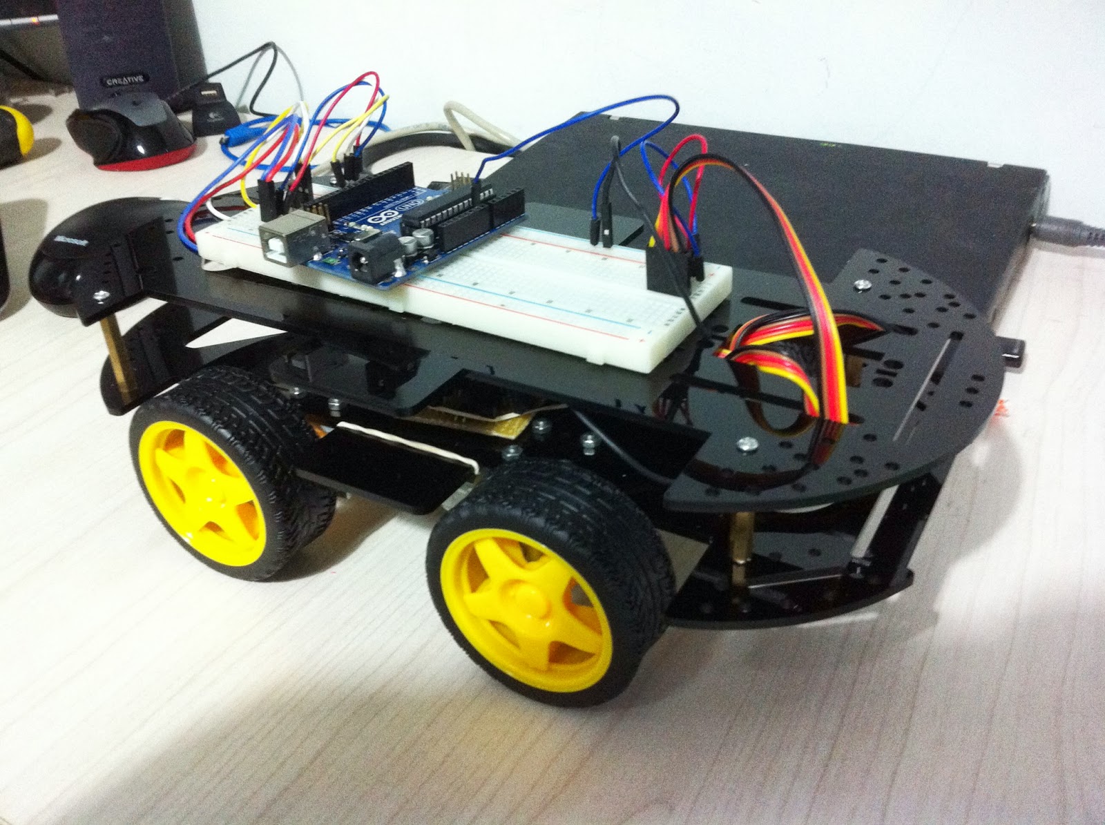
I then placed the upper platform of the car to mount a breadboard to continue the testing and hopefully make the cat run.


I took out an Arduino board and connected the pins to the H-Bridge using a breadboard and created a small sketch that will make the car move forward, backwards, rotate left and rotate right, each for 2 seconds.

The first tests didn't make the car move at all. Now that is a bummer. At first I though it's probably the battery, so I hooked them directly to the motor and the motor ran like there was no tomorrow. Back to the drawing board.

Looking at the schematics I created, I used 100K resistors so I will have a small as possible current leakage. I found a very cool site with a JAVA applet that can do a rather well simulations, check it out (The link has also the code to the H-Bridge circuit that I created):

Just to be clear, when I indicate a leakage I mean the current that passes though the H-Bridge Circuit and does not pass though the motor.

The good solution would be to place a 3 Darlington Transistors together and not just a pair, which would have solved the problem, but this would require a new PCB and throw away the one I already made. Another solution that is not so bad is using lower resistors to allow more current to drive the Transistors and allow more current to flow to the motor. Making the resistors 10K instead of 100K should resolve the problem. This, however, will have a current leakage problem when the motors run. If the input switches, both of them are set to off state there is a very minor leakage (in the PICO rating), when one of them is turned on, there is a leakage current of ~1.3mA. Well, it's not so bad, considering other alternatives I think this is the preferred solution.
OK, got the new 10K resistors replacing the 100K and this indeed did the job.
This is the updated Schematics

Don't want to bore anyone, but I also had a problem of the Arduino getting reset when using the same power supply as the motors. I didn't debug this, but I also decided not to mess with it too much, so I hooked a 9V battery to the Arduino, connected the grounds together with the H-Bridge ground and made the motors run on a 4 AA Cell batteries.

And now for the test. The test went as expected, but I still need to test the motors when I run them with PWM to see if I can make the Car go left and right in different speeds.

The next step would be to use another Arduino board connected to a joystick and wireless transmitter to make a remote control for the car. I will also need a wireless receiver on the car as well.

On last thing, I made a video of the test I did with the car after all the adjustments, enjoy.


Monday, September 9, 2013

SmartCar

It's been quite some time now since I started a new adventure/project. I really didn't have any idea to top what I did in my first blog (basila-arcade) and that what held me back.

What got me started again was a chat with a friend at work on an idea that he had to control his windows shades automatically based on sun light intensity and room temperature. He indicated that this can be done via a development board called "Arduino". I had no idea what that was, but it was my ticket back to electronics. I had studied Electronics in high school, but this does not make me an expert.

Not to bore anyone here, I'm already about to do it in another blog documenting all my findings in Electronics, so I'll leave the bed time for that blog.

After much testing, I have progressed well enough to see many nice projects of a toy smart car that used sensors that can detect path blockers and also allow it to follow lines.

I decided to go with building one for "my kid" - no really I'll probably give it to him to play with it.
I wanted to create this car from scratch as much as possible, so I decided to buy only the chassis and the motors.
The above is taken from DX site, I hope the link to the product will hold:

Cool, so now I have a car, but nothing to run the engine. To drive the engines in both directions (forward and backwards) I need a device that has a logic input that can control the direction of the motor rotation and the speed.
For the speed a PWM output will do the job from any chip, so I guess I'm set there but for the direction I will need an "H bridge" to help achieve this. I decided to go with building one from a bunch of 2N2222 transistors that I have, I got around 100 of them.
After a few tries, I almost gave up and bought an H bridge IC and be done with it, but still, what was I missing. Taking a closer look at the data sheet of the 2N2222 I saw the problem, I forgot about the current gain ratio which is ~100, this is what was holding it from driving the motor, but driving LEDs it did the job just fine. Well, someone already solved this and his name is Sidney Darlington that created the Darlington Pair which is just a simple configuration of a pair of transistors that the first one drives the second one making the gain of this configuration become G^2, so if the 2N2222 has a gain of ~100, with a Darlington pair it's 100^2 = 10000.

Ok, the breadbord gave the approval of the configuration and the motors rotated just perfectly, I also hooked an Arduino board with a PWM pin to the motor H bridge circuit to get a sense of the speed control all seems to function as predicted.

I created the schematics using Fritzing:

As you see, I created two H bridge configurations to allow a control of the left wheels and the right wheels.

I arranged the components on the PCB board also in Fritzing and connected the components - now I'm ready for soldering. Here is the final product: